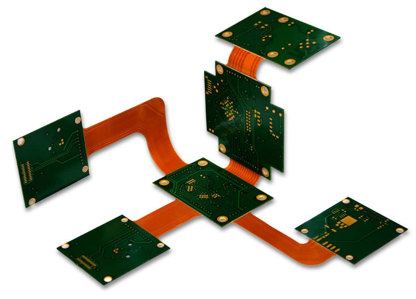
Flex circuits is a technology for assembling the electronic circuits by mounting electronic devices on polyimide which is a flexible PCB made of a plastic substrate. Flex PCB outweighs rigid PCBs.
Computerized Design:
Computer aided designing prepares the layouts. DFM review checks the trace widths, the space between the traces and the hole size. Photoplotter inputs the board data and converts into a pixel image.
Learning about PCB fabrication these days is getting important if you are tech loving person. Check out apct.com to know more about the topic.
On the Board:
A Polyimide base material is used on which a copper foil is laminated. The layers are held by these adhesive materials. Other choices for the base material are polyester and fluoropolymer. Expensive but high-temperature resistant Polyimide, flammable polyester, and high-frequency product’s polytetrafluoroethylene play the best in its own role.
The pixel image is written onto the film by the laser which is developed then. One film per Flex PCB layer is generated.
Inner layer lamination:
The copper is cleaned. To avoid short or open circuit, the panel is printed in a clean room. The photosensitive film is coated on the clean pan. The first film is loaded onto the coated panel and the second film.
The needed copper pattern of the Flexible PCB is covered by a hardened resist. Unwanted copper can be removed using a powerful alkaline solution.
Automated optical inspection system scans the board to correct any errors if found. Oxide treatment is performed to protect the newly formed base copper from oxidation.
Multi-layer lamination:
The required sheets, a copper foil, and an aluminum press plate are added on a heavy base plate. More panels are created similarly. The finished stack is loaded to bond the Flex PCB layers together. The aluminum plate is removed to reveal the smooth copper plate. Cutting out the unwanted, the panels can be drilled.
Drilling:
The computer program for the corresponding drilling of XY coordinate is selected by the operator. High-speed drilling is essential for clean holes. CNC, computer numerical control is used in fabrication. This machine does repeat, accurate movements which are computer controlled. The computer-generated code is converted into electric signals that assist in drilling holes in the Flex PCB.
Once the metallization process is completed, the Solder mask is printed on a side to protect the copper. Solder mask is coated by spraying and finally dried.
Out of the clean room:
Protective plating is done to prevent oxidization. Inkjet printers allow printing which forms a uniform pattern. A final testing before shipping is performed.
Thin, lightweight, flexibility helps Flex PCBs in plundering the chances of other PCBs in the high-reliability military and medical applications.
These were the most common ways in which Flexible PCB manufacturing is performed. Learn more about PCBs on our site.


